Cutting
Tube laser cutting
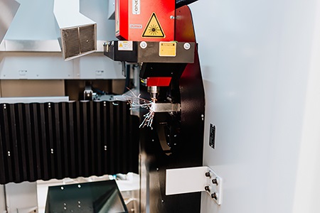
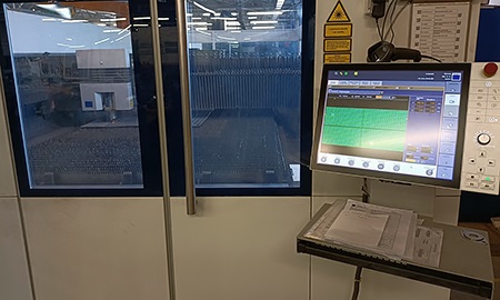
Maximum precision is achieved during cutting because the centering collet chuck (which is located closest to the cutting head) rotates in sync with the revolving collet chuck. During the cutting process, the automatic feeder system measures each workpiece arriving in the bundle and sends them to the cutting line until the cutting is in progress, and the feeder system prepares the next workpiece. The cutting head is equipped with a capacitive distance sensor that continuously adjusts the distance between the nozzle and the workpiece with the fast-axis control of the "Z" axis. It is protected against overheating by water cooling. The machine is controlled by a Sinumerik SL84OD CNC control system based on a 64-bit microprocessor. It has its own Durma interface and a complete cutting setting database. Based on reference values, you can easily adjust the cutting quality.
General usage areas: agricultural machinery manufacturing, protective devices for shopping centers, rack systems, supporting structures, frame structures for electrical cabinets, internal reinforcements for covers, as well as decorative elements, candle holders, and accessories for home use.
We undertake the laser machining of round tubes and square profiles in the following range with tube laser cutting:
|
Material type |
Minimum outer circle diameter (mm) |
Maximal outer circle diameter (mm) |
Minimum wall thickness (mm) |
Maximal wall thickness (mm) |
Dosable raw material max. length (mm) |
Finished workpiece max. length (mm) |
|
Carbon steel |
Pipes min. diameter: 20 Pipes max. diameter: 170 Welded profiles min.: 20x20 Welded profiles max: 120x120 Brick profiles min.: 25x20 Brick profiles max.: 150x100 |
0,5 |
10 |
6500 |
4500 |
|
|
Stainless steel |
0,5 |
6 |
6500 |
4500 |
||
|
Aluminium |
0,5 |
8 |
6500 |
4500 |
||
Flat laser cutting
Our company uses modern cutting machines that enable the production of high-precision parts with short turnaround times. The material required for production is provided by our sheet metal warehouse, which has a huge inventory, but we also process material provided by the customer.
|
Machine |
Max board size |
Carbon steel |
Stainless |
Aluminium |
Brass |
Copper |
|
Trumpf CO2 |
2000x4000 mm |
20 mm |
12 mm |
8 mm |
- |
- |
|
Mitsubishi 8 kW |
1500x3000 mm |
30 mm |
30 mm |
30 mm |
18 mm |
10 mm |
Stanc cutting
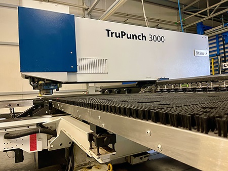
The machine's machining capabilities are as follows:
|
Machine |
Max board size |
Carbon steel |
Stainless |
Aluminium |
Brass |
Copper |
|
Stanc |
1250x2500 mm |
3 mm |
3 mm |
3 mm |
5 mm |
5 mm |
|
Combined |
1250x2500 mm |
3 mm |
3 mm |
3 mm |
5 mm |
5 mm |
Edge bending
Over the years, we have strived to be prepared for every task and inquiry in the field of fine sheet metal edge bending. This is reflected in the quantity and quality of our diverse tool sets and our versatile machine park, which includes two 30-ton Amada machines, one 22-ton Cone machine, two 2-meter Amada machines, one 3-meter Amada machine, and one 320-ton Durma edge bending machine. For high-volume recurring machining tasks, our Salvagnini panel bending machine provides an efficient and productive solution to bring your ideas to life.
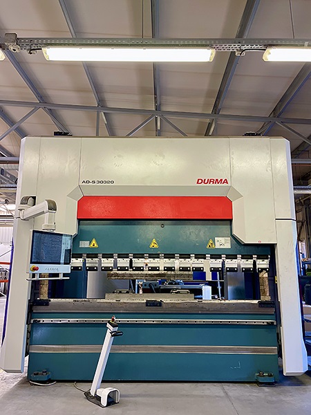
DURMA AD-S 30320 Hydraulic CNC Edge Bender
In December 2020, Matic Ltd. installed the AD-S 30320 edge bending machine, increasing capacity and expanding the range of products manufactured by the company.
Our AD-S 30320 CNC-controlled edge bending machine represents state-of-the-art technology with (Y1-Y2, X1-X2, R1-R2, Z1-Z2) axes, working with high precision and force. This means that even less experienced machine operators can produce parts with the most complex bending requirements. Thanks to our expertise and excellent technical equipment, even the most complex sheet metal parts and other products can be bent without any problems. For the bending tasks we undertake, 320 tons of pressing force is available over a length of 3 meters, enabling the edge bending of sheets up to 10mm thick per meter. Our primary goal is to achieve the smallest radii possible using the smallest tools.
Our edge bending machine is driven by CNC-controlled motors on every axis, allowing for precise adjustments, collisions, and measurements, ensuring flawless execution for our clients. The key element for perfect bending is a stable and accurate rear stop system.
During our expert technical preparation, we use computer-aided design and model creation to create sheet metal layouts optimized for bending parameters, ensuring perfect parts after bending.
Our machine works with EURO type upper and lower tools, which are easily obtainable, making tool procurement stress-free for new projects. Additionally, the quick tool clamping system allows for fast tool changes.
One safety feature is the laser intrusion protection, and the other is the front sliding sheet holder, which ensures proper sheet support.
Panel bending
The biggest advantage of these machines is their universal tools, which eliminates the need for setup and tooling time. The machine adapts to the geometry based on the 3D model (stp) generated program and creates the planned bends on the finished product, resulting in maximum production without scrap and with parts meeting design specifications.
An interesting feature of the machine is that it requires less than 20 liters of oil to operate, as it has both electric and pneumatic drives.
The machine is easy to operate and its user interface is user-friendly on all platforms.
Salvagnini P4Lean-2120 panel bender/folder
Main features:
► MAC 2.0: Adaptive bending correction system. During the bending process, the machine measures the force, compares it to the necessary force in the database, and performs the necessary corrections if there is any deviation due to changes in material quality.
► Rolling precision bending, which completely eliminates damage during bending.
► Ability to bend partially or fully enclosed edges.
► Ability to bend painted or foil-coated sheets without damage.
► Possibility to take unique reference points.
► Ball screw-driven manipulator, ensuring speed and precision.
► Integrated sheet thickness measuring system.
Bending parameters:
► Maximum longitudinal dimension of incoming material: 2495 mm
► Maximum transverse dimension of incoming material: 1524 mm
► Maximum diagonal dimension of incoming material: 2500 mm
► Maximum bendable length: 2180 mm
► Maximum bendable height: 200 mm
| Material type | Minimum material thickness (mm) | Maximal wall thickness (mm) | Dosable raw material max. length (mm) | Max. length of tools | Max. length of the inner bend (short side) | Max. length of the inner bend (long side) |
| Carbon steel | 0,4 | 2,5 | 6500 | 2180 mm | 30 mm | 45 mm |
| Stainless steel | 0,4 | 2,5 | 6500 | |||
| Aluminium | 0,4 | 4 | 6500 |
Fiber sanding
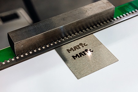
Laser engraving
Spot welding
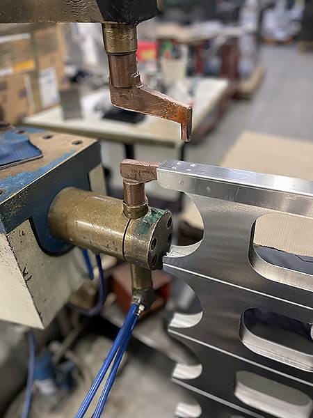
The process is practically divided into three stages:
1. By switching on the current (I), an electrical contact is created between the workpieces. The solid metal heats up and expands, thereby increasing the gap between the workpieces. Then, under the effect of electrode force, the molten metal is squeezed out into the gap between the workpieces, forming the closing zone of the weld.
2. The contact area continues to increase, and a lens of diameter depending on the thickness of the workpiece is formed. The surface oxide layer breaks up and mixes with the molten metal, which further expands and undergoes plastic deformation.
3. After switching off the welding current, the metal cools and crystallizes. The crystallization process can be regulated by the change of pressing force. The thermomechanical stress of the welded metal affects the properties of the lens and the metal in its immediate vicinity.
In spot welding, different welding cycles can be set according to the material quality, thickness of the workpieces, the type of the bond, etc. The welding cycle is mainly determined by the current strength, pressing force, and welding time.
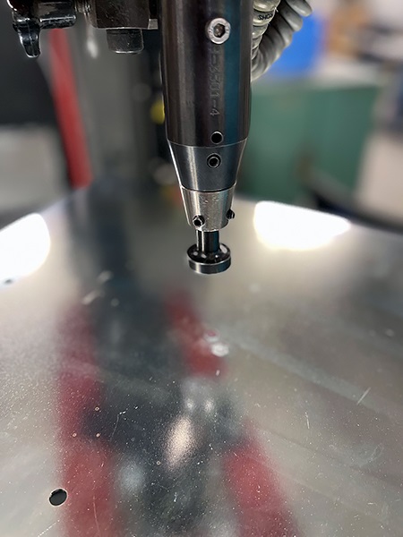
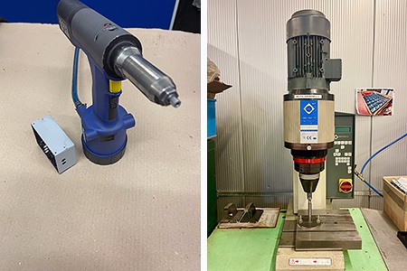
Stud welding
Technological description: (source: www.soyer.hu - accessed: 04/01/2023
Arc drawing technology:
In this welding process, a welding power controller serves as the energy source, which introduces a continuous arc that can be controlled in duration and current. The welding time is usually 0.1 - 0.2 seconds. It is possible to use shielding gas or a ceramic ring as an auxiliary device.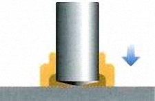 The welding pin touches the welding surface.
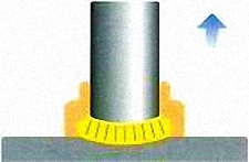 The welding pin moves away from the welding surface, the arc ignites.
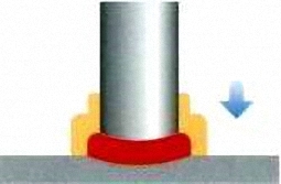 The welding pin is immersed in the melt, the melt solidifies, and the joint is created.
Stud welding technology:
In this stud welding process, the current source is provided by a capacitor that discharges its voltage through the tip of the welding stud in an extremely short period of 1-3 ms (0.001-0.003 seconds). The use of auxiliary devices such as a ceramic ring or shielding gas is not necessary.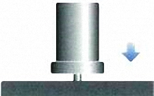 The tip of the welding pin touches the welding surface.
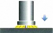 The arc forms a thin melt layer between the welding pin and the work surface.
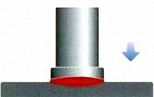 The welding pin is immersed in the melt, the melt solidifies, and the joint is created.
(Source: www.soyer.hu - access: 01.04.2023)
Fastener pressing (Pinning)
Riveting
Welding
Manual arc welding
In addition, our company has ISO3834 welding shop certification, where the most common welding processes are validated, our employees have all the relevant certifications, and new requests are processed with the help of our welding supervisor.
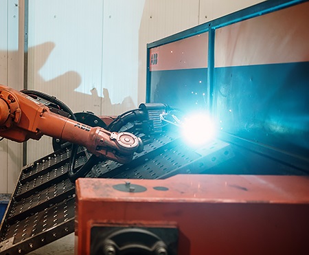
Robot welding
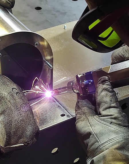
Laser welding
Advantages:
► Much less distortion compared to other welding processes
► Faster and more precise process
► The heat is concentrated on the focal point generated by the laser
► Narrow heat-affected zone
► Easy integration into a process
► Significantly less post-processing effort
► The welding head is also a cleaning head (2 minutes conversion time)
► The welds produced in this way are more cost-effective
Disadvantages:
► High machine acquisition cost
► Thickness of the sheet metal sets limits
Matic's machine park has a 2 kW machine that can weld the following sheets without any problem:
Carbon steel / stainless steel sheet: up to 8mm
Aluminum: up to 6mm
The machine is equipped with a combined head, which, with a quick changeover, provides us with a full-fledged laser cleaning device.
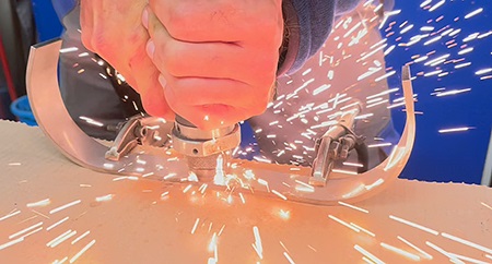
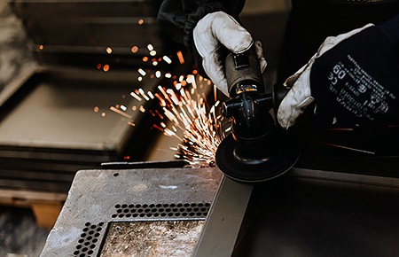
Manual grinding, weld seam processing
Pressing
We distinguish between four and two-column hydraulic presses, as well as closed and framed ones.
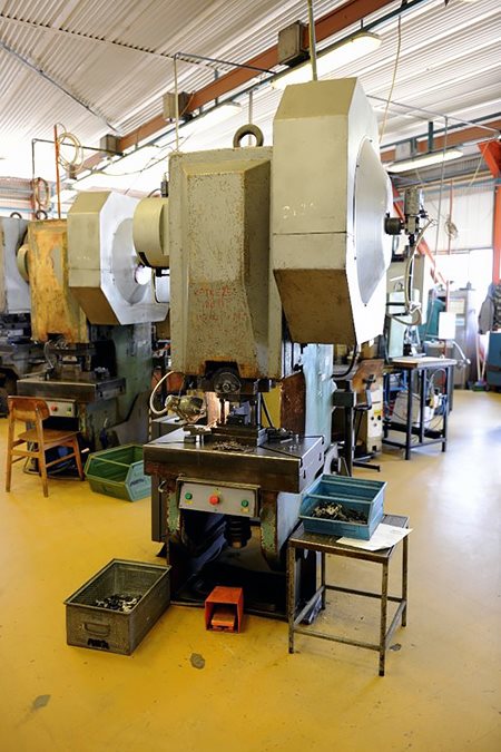
Mechanical presses:
Among the various types of presses, we have eccentric presses up to 250 tons. We are talking about single-station eccentric presses that are designed for more general purposes, such as cutting and shaping sheet metal in our case. The frame of the machines is "C"-shaped, and the most important thing is that the flexible deformation of the frame of single-station presses is significantly greater than that of other press types. The main shaft is located perpendicular to the table, so the eccentric is located at the end of the main shaft. The machines require purpose-built tools necessary for the machining task, which can be single and combined (multi-stage) press tools. This machining format is worth choosing for mass production, and we can provide assistance in tool making in-house.
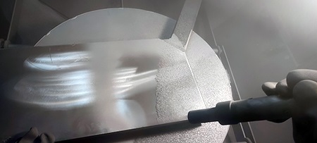
Sandblasting
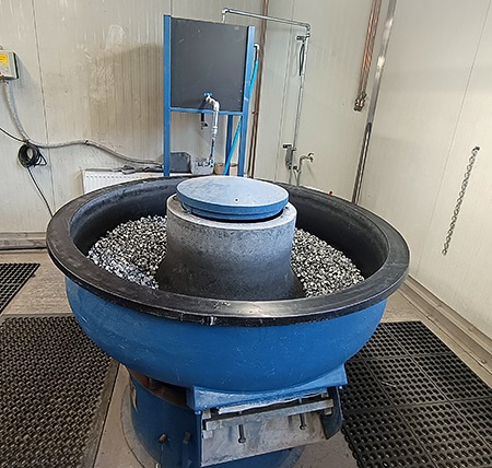
Abrasion
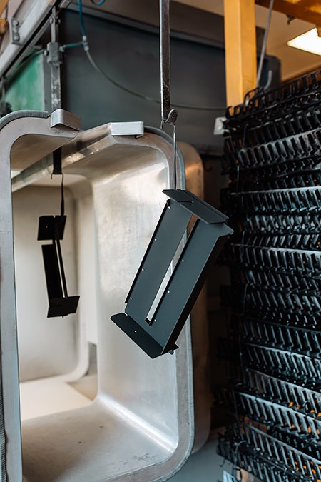
Powder coating
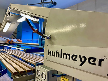
CNC disk sawing
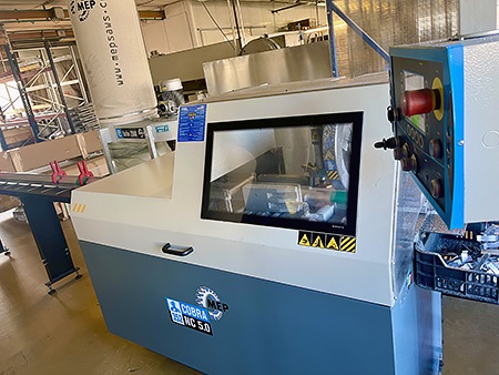
Our machining capabilities are as follows:
For circular cross-sections, the maximum diameter is D120mm. For square materials, the maximum dimensions are 100x100mm, and for rectangular materials, the maximum dimensions are 180x70mm. For solid materials, the machine can be used for up to 80x80mm.
We have several solutions for reducing or eliminating material waste.
A lubrication spraying system ensures the quality of cutting and the productivity of feed.
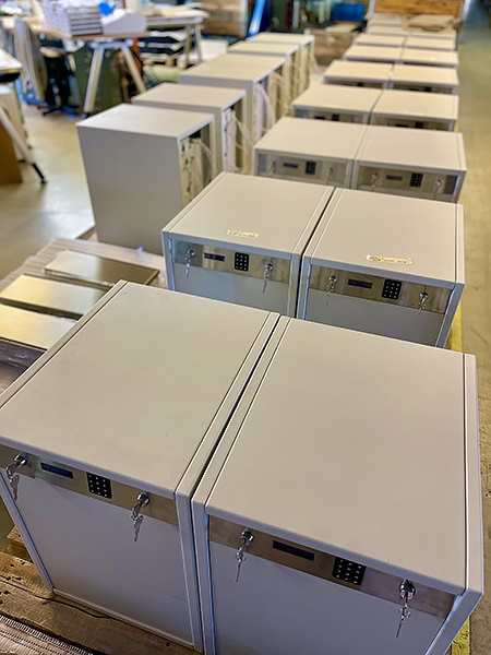
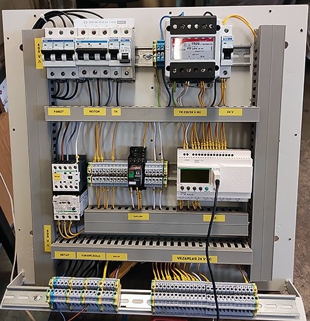
Mechanical and electronic assembly